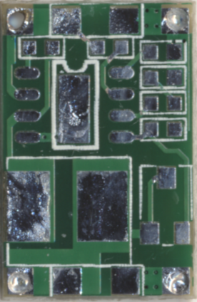
This is a reverse-engineered component placement diagram from one of the common Mini-360 switch mode power supply circuits. The software to calculate resistor values can be found here and the schematic PDF is here. Essentially, it's the "typical application" copied 1:1 -- I've labled the components as they are in the datasheet, so that it's easy to find your way around there.
Note that there are deliberately underpowered, broken Mini-360 circuits in circulation. These will have horrible efficiency and be a general pain-in-the-butt. Here's what was different in my "broken" version compared to the version I got that was good:
This will lead to regulator instability and general, horrible performance (40% efficiency and worse). Note that even the ones that are "properly" working have some deficiencies:
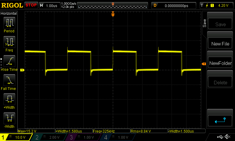
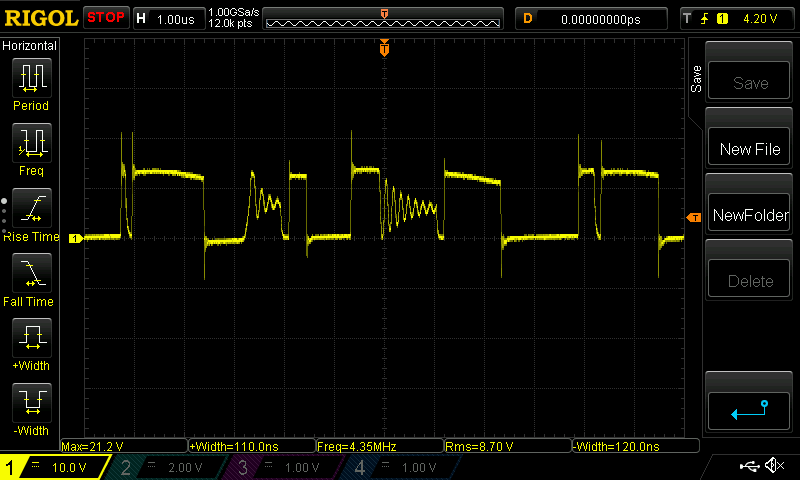
To figure out if you're suffering from regulator instability, the easiest way is to directly measure at the inductor (side facing out). If everything is great, you'll see something like this:
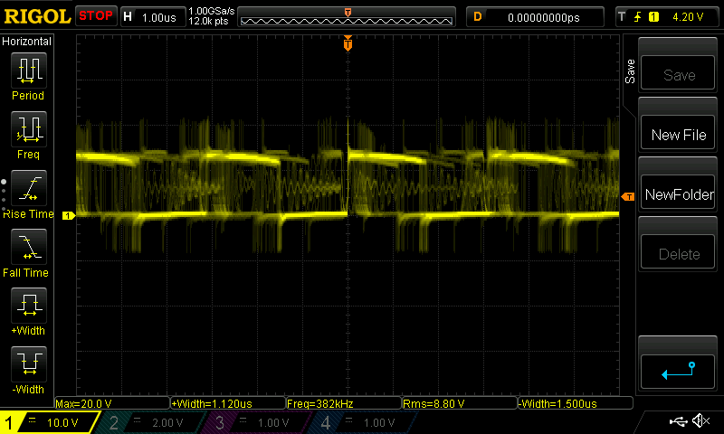
If you're experiencing intermittent regulator instabilities, you'll see something like this (if you're lucky):
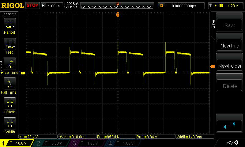
If it's even worse, you might see something like this:
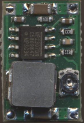
Here's the hardware: